Kenwood TM-701A: Difference between revisions
m →Review |
|||
| (2 intermediate revisions by the same user not shown) | |||
| Line 7: | Line 7: | ||
==Options== | ==Options== | ||
==Review== | ==Review== | ||
It is an older 2m/440 rig. It works. The battery is not that difficult to change but a little digging is required. The | It is an older 2m/440 rig. It works. The battery is not that difficult to change but a little digging is required. The light for the display tends to go out, there's actually two bulbs, one for the left and one for the right side of the lcd display. The display can still be read daytime. The stock microphone cord tends to crumble. The stock microphone is kind of flimsy. | ||
The radio itself is built pretty solid and provides a long reliable service life. Built in CTCSS for repeater operation. | The radio itself is built pretty solid and provides a long reliable service life. Built in CTCSS for repeater operation. | ||
| Line 15: | Line 15: | ||
The extended transmit mod does not allow for extended 70cm operation, it will not cover FRS/GMRS. | The extended transmit mod does not allow for extended 70cm operation, it will not cover FRS/GMRS. | ||
What is stupid is that Kenwood put an so-239 | Separate 2m and 70cm connectors is something that is a personal preference yet when considering it thoroughly it has numerous advantages. What is stupid is that Kenwood put an so-239 for the 70cm connector which should be an N type connector. This is the kind of thing that puts the "amateur" in amateur radio. | ||
==Basic Usage== | ==Basic Usage== | ||
Latest revision as of 21:24, 5 February 2017
Operating dual band on 2-meter and 70-cm ham radio bands, this transceiver is very compact and features 20 memory channels and multi-scan functions. It has the same chassis as Kenwood TM-231a/431a series and shares many of the accessories. Power output is 25/5 watts on 2 meters and 35/10/5 watts on 440 MHz. Frequency step is selectable at: 5, 10, 15, 20, 12.5 and 25 kHz. CTCSS tone encode is built-in.
- Extended receive range is 136-174 MHz and 438-450 MHz.
Options
Review
It is an older 2m/440 rig. It works. The battery is not that difficult to change but a little digging is required. The light for the display tends to go out, there's actually two bulbs, one for the left and one for the right side of the lcd display. The display can still be read daytime. The stock microphone cord tends to crumble. The stock microphone is kind of flimsy.
The radio itself is built pretty solid and provides a long reliable service life. Built in CTCSS for repeater operation.
The cross-band repeat mod is not really worth the trouble since it provides only simplex (one way) cross band.
The extended transmit mod does not allow for extended 70cm operation, it will not cover FRS/GMRS.
Separate 2m and 70cm connectors is something that is a personal preference yet when considering it thoroughly it has numerous advantages. What is stupid is that Kenwood put an so-239 for the 70cm connector which should be an N type connector. This is the kind of thing that puts the "amateur" in amateur radio.
Basic Usage
Programming
Troubleshooting
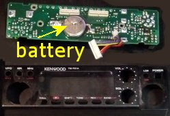
The memory battery will go bad and cause it to lose all program memories when disconnected from power. To replace the battery a lot of disassembly is required.
Battery is on board behind the front display.
Modifications
Available modifications:
- cross-band repeater
- transmitting and receiving from 136-175MHz
- prevent intermittent memory loss due to pulses on the CPU interrupt line
Extended Transmit
1 Disconnect the power and antenna.
2. Remove the top and bottom cover.
3. Remove knobs from front panel and the nuts from the mic and channel switch.
4. Remove 4 screws holding the front panel and the 3 screws on the control board.
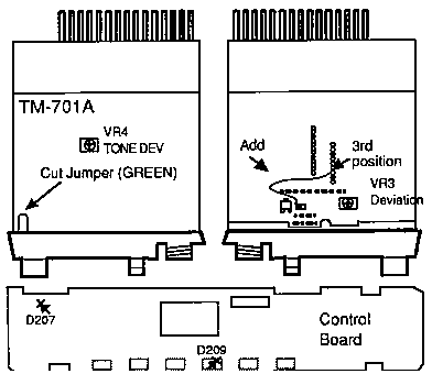
5. Locate the green jumper wire sticking out the front panel, behind the VFO button
6. Cut the green jumper and tape the edges to prevent them from shorting.
Cutting the green jumper allows the TM-701A to transmit from 142 to 151.995 MHz.
Cross Band Repeat Mod
Perform steps 1 - 6 above and continue...
7. Optional: Install diodes D207 & D209 on control board X57-3350-00.
8. Solder a jumper to the foil side of the TX-RX board as shown in drawing.
9. Reassemble the radio.
10. Reset the microprocessor (Press and hold [MR] while turning on the power).
The repeater cross-band operation allows the TM-701A to receive on one band and re-transmit the signal on the other band. The TM-701A alternately displays the two bands until a signal is received. The transceiver will then display the band that is re-transmitting the signal. The shift function cannot be used during the repeater cross-band operation. If the TONE or CTCSS function is required, only one EIA tone can be used for the two bands.
CROSS BAND OPERATING PROCEDURE
Turn on the Repeater mode-
- Press and hold [F] and then press [DUP].
- Then Press [F} longer than 1 Second. The F indicator will blink.
- Press[LOW]. Three dots should appear in the display when the mode is on.
Turn off
- Press [VFO].
The information was provided to you for free. Use at your own risk. You can copy the information and you do not have to worry about advertisements or JavaScript here!


