Midland Model 13-857 CB Radio: Difference between revisions
mNo edit summary |
mNo edit summary |
||
| (3 intermediate revisions by one other user not shown) | |||
| Line 7: | Line 7: | ||
*mode: AM | *mode: AM | ||
*xmit power: 4 W | *xmit power: 4 W | ||
*frequency control: XTAL-synthesis | *frequency control: Crystal-synthesis ( XTAL-synthesis ) | ||
*voltage: 13.8 VDC | *voltage: 13.8 VDC | ||
*period: 1970s | *period: 1970s | ||
| Line 24: | Line 24: | ||
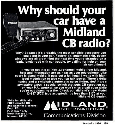
[[File:midlandscbad1976big.gif]] | [[File:midlandscbad1976big.gif]] | ||
==Specification== | |||
The MIDLAND 13-857 and model 77-857 have similar designs, but different PCB and frequency conversions. The model 13-857 has a 23 channel Crystal. <del>These Midland radios were Cybernet board based radios with the PLL02A phase-locked loop circuit and three crystals.</del> | |||
==Service== | ==Service== | ||
| Line 68: | Line 71: | ||
[[Category:2-Way Radio]] | [[Category:2-Way Radio]] | ||
[[Category:CB Radio]] | [[Category:CB Radio]] | ||
[[Category:FCC Part 95]] | |||
Latest revision as of 09:34, 28 April 2024
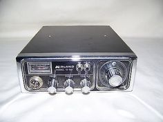
Midland 13-857 CB Radio
This was a black and silver CB radio with front dials with squelch and delta knobs, attached cord to walkie. wires attached to back. The start date of manufacture was 1976,
- frequency Range: 26.965-27.255 MHz
- channels: 23
- mode: AM
- xmit power: 4 W
- frequency control: Crystal-synthesis ( XTAL-synthesis )
- voltage: 13.8 VDC
- period: 1970s
- size: radio L: 7.5" H: 2.5" D: 9.5" walkie L: 3" H: 4" D: 2" cord 1'5"
Variations:
- Model 13-857
- Model 13-857B
- Model 77-857
The model 77-857 was a 40 channel version of the original 23 channel 13-857.
Advertisement from 1976
Specification
The MIDLAND 13-857 and model 77-857 have similar designs, but different PCB and frequency conversions. The model 13-857 has a 23 channel Crystal. These Midland radios were Cybernet board based radios with the PLL02A phase-locked loop circuit and three crystals.
Service
Microphone Wiring
PIN           FUNCTION
1             audio
2             ground / common
3             receive
4             PTT
Modification
Adjustments chart:
Model          AM Power        SSB Power       Modulation
-------------------------------------------------------------------
13-857         L8,L9 	        ¾ 	        RV2 or Cut D10
13-857B        L110,L109 	¾ 	        RV102 or Cut D111
77-857         L7,L11,L12 	¾ 	        RV2 or Remove C96
-------------------------------------------------------------------
Modulation Adjustment RV2
Tune the following coils with maxium with a 1000 Hz tone injected through the microphone and using a peak reading wattmeter on channel 13: L7, L8, (L9 is a TVI filter - tune for minimum interference on TV.)
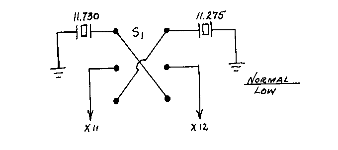
New channels can be obtained either by switching X11 and X12 or by substituting other crystals for them.
X11 = 11.730 receive oscillator
X12 = 11.275 transmit oscillator
      ------
        .455
As you can see, X11 is 455 KC higher than X12. This is how you get your receive IF frequency of 455 KC. If you swap X11 and X12 around, you will get low channels. This can be done easily by using a switch. Be sure to use solid hookup wire between the switch and board. Keep the leads as short as possible. The wiring configuration should look like what is showed in the following diagram.
- S1 use a DPDT toggle switch
If you use other crystals, they must be 455 KC apart so receive and transmit will work together correctly.


