Yaesu FT-817
The FT-817 is a compact, innovative multiband, multimode portable transceiver for the amateur radio HF/VHF/UHF bands. Providing coverage of the 160-10 meter bands plus the 6 m, 2 m, and 70 cm bands, the FT-817 includes operation on the SSB, CW, AM, FM, and Digital modes, yielding the most comprehensive performance package available for portable operation.
Designed for use either from an external DC power source or internal batteries, the FT-817 provides five watts of power output from a 13.8-Volt external power supply.
Front Panel Control
FUNC Keys: These three keys select many of the most important operating features of the transceiver. When pressing the [F] key, the current function of that key appears above each of the [A], [B], [C] keys (along the bottom of the LCD); rotating the [SEL] knob scrolls the display through eleven rows of functions available for use via the [A], [B], [C] keys.
Band Down/Up Keys: Pressing either of these keys momentarily will cause the frequency to be moved up or down by one frequency band.
Mode Keys: Pressing either of these keys momentarily will change the Operating mode.
Home Key: Pressing this key momentarily recalls a favorite "HOME" frequency memory.
Clar Key:
Ant Jack:
Memory Channels
Normal Memory Storage
There are 200 normal memory channels numbered 1 - 200
1. Tune in the desired frequency, and set the operating mode and bandwidth. If this is an FM channel, set up any required CTCSS/DCS and repeater shift configurations. Standard (default) repeater shifts do not require you to utilize the "split" frequency memory technique.
2. Press the [F] key momentarily, then rotate the [SEL] knob as needed until Operating Function Row 2 [ MW, MC, TAG ] appears on the display.
3. Press the [A] key momentarily to enter the "Memory Check" mode, which is used to find an unused memory channel. The frequency stored (if any) on the current memory channel will be shown in the display.
4. Rotate the [SEL] knob to select the channel number on which you wish to store the current frequency data.
5. Press and hold in the [A](MW) for one second until you hear a double beep; the second beep confirms that the frequency information was successfully stored.
Delete Memory Channel
The deletion process is not a "hard" erasure, so if you erase a channel by mistake using this procedure, the memory channel contents can be recovered.
1. Press the [F] key momentarily, then rotate the [SEL] knob, as needed, until Operating Function Row 2 [ MW, MC, TAG ] appears on the display.
2. Press the [A](MW) key momentarily, then rotate the [SEL] knob to select the memory channel to be deleted.
3. Press the [B](MC) key momentarily. The frequency display field on the LCD will go blank, and the memory channel number will blink.
4. Wait about three seconds; when the memory channel number stops blinking, the data will now be "masked" and will not be available for operation.
5. To restore the masked frequency data, repeat the above steps. However, if you store new frequency information on a channel containing masked data, the masked data will be over-written and lost.
6. Memory Channel 1 is used for Priority operation, and frequency information may only be over-written (not masked) on this channel.
CHIRP Program via PC
In February 2012, CHIRP gained support for programming the Yaesu FT-8×7 family of radios, thanks to efforts by Marco IZ3GME.
MARS CAP and Widebanding
internal modification
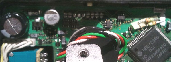
The solder pads controlling transmit and receive function are located behind the front panel. The front panel needs to be disconnected and removed from the chassis to perform the mod. Soldering equipment is required.

Illustration: ft-817 serial range ON1503xx factory jumper solder pad configuration. From left to right:
- JP4009 factory set to: OPEN
- JP4008 factory set to: OPEN
- JP4007 factory set to: CLOSED
- JP4006 factory set to: CLOSED
- JP4005 factory set to: CLOSED
- JP4004 factory set to: OPEN
- JP4003 factory set to: OPEN
- JP4002 factory set to: OPEN
- JP4001 factory set to: OPEN
The mars modification guide from Yaesu indicates a different default configuration for the jumpers from the factory. This is often the problem with Yaesu. They make subtle changes resulting in variations within the same product line during production.
According to Yaesu's guide, Jumper pads 6,7,8 need to be CLOSED, 4,5,6 need to be OPEN, and 1,2,3 remain OPEN / unchanged. After committing this configuration to my Yaesu the result was the full VHF / UHF range became unlocked. As for HF...
HF transmission was not completely opened, however, some placed did open up, some of the MARS specific locations and also some others, yet some MARS frequencies were still blocked. Citizen Band remained blocked. WWV was open to transmit! Weird.
- 4041 ... no ... MARS
- 7302 ... yes ... MARS
- 7500 ... yes ... Military
- 7540 ... no ... MARS
- 7635 ... no ... Civil Air Patrol
- 10000 ... yes ... WWV
- 14441 ... yes ... MARS / other
- 14487 ... yes ... MARS
- 27185 ... no ... Citizen Band
Your results may vary depending on the default jumper positions during the time of your ft-817 production.
software modification
Software: FT-817 WidebanderV4.exe
Widebanding the ft817 in this way makes no Permanent changes to the radio. To set it back to the factory band plan you can do a full reset or run Widebander and press the button to put your radio back to standard. It just that simple and it really works. You can also use Widebander on the FT-857 and FT-897.
source: http://ham-radio.ca/pages/radio-equipment/ft-817.php#wide
WidebanderV4.exe
Note: This software does not work with the ND model, only the original ft-817. If you have the ft-817ND you will have to perform the hardware modification as described above.
When using a USB FTDI programming cable:
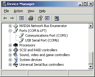
Using FT-817 WidebanderV4 was easy once Windows was forced to allow it on one of the lower comports. This software must have been designed for computers prior to the virtual COM port driver (VCP). You will not be able to use the software if once your FTDI data cable is using a VCP higher than com:6. Force it to com:6

Windows Key + R, type "devmgmt.exe" press enter. Look for Ports (COM&LPT) and find the USB Serial Port, right click, Properties, Por Settings tab, Advanced button, and set your com port.
The software did not need to be "installed" as it ran directly from the exe file! This is good.
With the FTDI cable connected place the radio in cloning mode. Do this by holding down BOTH mode buttons while turning the power on. You should see "CLONE MODE" on the display. Run WidebanderV4.exe and click the option in the "Wideband Radio Now" group "817."
Accessories
There are many accessories for the ft-817. Some noteworthy accessories are mentioned here.
external display

CatDisplay plugs into a Yaesu transceiver CAT port. It reads EEPROM data from the transceiver, detects & decodes any changes then updates the display. The custom algorithm also monitors transceiver use and slows down data requests when idle.
CatDisplay reads information from the transceiver only. It does not write information to the transceiver and cannot be used to control the transceiver. Unlike computer programs that control the transceiver, CatDisplay will not cause EEPROM wear and will therefore not cause damage to the transceiver.
QRP whip Antenna Miracle / Miracle Ducker
- Review: The all-band rig-mounted whip for the FT-817 (and lots of other radios too...)
- Review: Miracle Ducker IL
- Miracle Ducker TL on Universal Radio
The Miracle Whip Antenna its cousin the Miracle Ducker are compact HF/VHF antennas for use with small portable handheld rigs like the FT817. The antenna functions via a multi-tapped toroidial inductor.
An article here explains, "Its gain without a wire counterpoise was measured as 29dB below a dipole and 10dB below with one on 20m i.e. some 5 S points down using just the MW alone (i.e. poor) but only 1.5-2 S points down if a decent counterpoise or earth was used too (not at all bad)."
