BNC Connector
BNC connectors, named after "Bayonet Neill-Concelman" (from their bayonet-style locking mechanism and inventors Paul Neill and Carl Concelman), are widely used coaxial RF connectors. The BNC was originally designed for military use and has gained wide acceptance in video and RF applications up to 2 GHz.
The BNC connector is used for signal connections such as:
- analog and serial digital interface video signals
- radio antennas
- aerospace electronics (avionics)
- nuclear instrumentation
- test equipment.
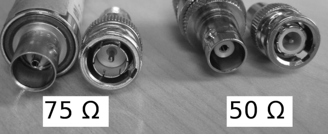
While there are variations in BNC designs, the two types common with difference in the center pin diameter—are the 50-ohm and 75-ohm BNC connectors. These impedance ratings are the primary distinguishing factors, and they do indeed affect the physical construction, including the center pin and dielectric dimensions. The 75 ohm types can sometimes be recognized by the reduced or absent dielectric in the mating ends but this is by no means reliable. There was a proposal in the early 1970s for the dielectric material to be coloured red in 75 ohm connectors, and while this is occasionally implemented, it did not become standard.
Nomenclature
50-ohm BNC is designed for applications where the characteristic impedance of the system is 50 ohms. This is the more common variant, used in professional audio/video, test equipment, radio communications, and early computer networking (e.g., 10BASE2 Ethernet).
75-ohm BNC is designed for 75-ohm impedance systems, typically found in telecommunications, broadcast video (e.g., analog TV, SDI), and some high-frequency applications like cable TV or certain oscilloscope probes.
The "ohm" rating refers to the characteristic impedance of the connector and the coaxial cable it mates with, which determines how signals propagate without reflections or loss. Despite the similar external appearance, the internal geometry differs to maintain these impedance values.
Differences
Impedance differences between the two are indicated by subtle physical differences which can create confusion and connection problems for users that are unaware.
The picture example is common but not exclusively applied in regards to dielectric differences. Pin size is specific to each impedance. Other characteristics may vary. The 75 ohm connector has slightly different dimensions from the 50 ohm variant, but the two can nevertheless be made to mate. Despite some sources claiming BNC connections of different impedances will mate non-destructively, the connection will be poor and damage will likely occur. Avoid mating the 50 ohm type to the 75 ohm type.
Center Pin
In a 50-ohm BNC, the center pin (male) is slightly thicker, and the dielectric insulator surrounding it is sized to maintain a 50-ohm impedance. The pin diameter is approximately 1.3 mm.
In a 75-ohm BNC, the center pin is thinner, around 0.8 mm, and the dielectric is adjusted (often with a larger air gap or different material) to achieve the 75-ohm impedance. This reduces capacitance per unit length.
Dielectric and Shielding
The 50-ohm version uses a solid dielectric (often PTFE or polyethylene) optimized for lower impedance.
The 75-ohm version may have a partially air-spaced or lower-density dielectric to increase impedance, which is why the pin and socket dimensions differ.
Compatibility
Mechanically, 50-ohm and 75-ohm BNC connectors can often mate with each other due to the bayonet locking mechanism being identical. However, this is not recommended for high-frequency or precision applications because a 50-ohm plug in a 75-ohm jack may damage the thinner 75-ohm socket due to the thicker pin. A 75-ohm plug in a 50-ohm jack may result in poor contact or signal integrity issues.
At low frequencies (e.g., audio or baseband video), the mismatch might be tolerable, but at RF frequencies, it causes signal reflections and losses.
They look nearly identical externally, but some 75-ohm BNCs have a colored insulator (e.g., red or blue) or a slightly tapered pin to distinguish them. However, this isn’t universal, so checking specs or measuring impedance is the surest way to tell them apart.
Applications
50-ohm is common in RF equipment, antennas, and data networks where 50-ohm cables (like RG-58 or RG-213) are standard.
75-ohm is dominant in video and telecom, paired with cables like RG-59 or RG-6, where higher impedance reduces signal attenuation over long runs.
The key difference lies in the impedance (50 vs. 75 ohms), which dictates the center pin diameter and dielectric design. The 50-ohm BNC has a thicker pin for lower impedance systems, while the 75-ohm BNC has a thinner pin for higher impedance applications. Always match the connector to the cable and system impedance for optimal performance, especially at higher frequencies.
