Difference between revisions of "Coax Compression Connector Installation"
| Line 22: | Line 22: | ||
No braiding should be sticking out the rear of the connector, that causes signal loss. You should be able to pull on the connector with reasonable or light force without it coming off. | No braiding should be sticking out the rear of the connector, that causes signal loss. You should be able to pull on the connector with reasonable or light force without it coming off. | ||
| + | |||
| + | |||
| + | [[Category:Electronics]] | ||
| + | [[Category:CCTV]] | ||
| + | [[Category:Satellite & Cable TV]] | ||
Revision as of 23:09, 16 July 2015
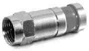
This is the F Type Compression connector being used by the satellite and cable television industry. The F Type compression connector should NOT be confused with earlier "screw on" or push on connectors that don't stay put. RG-6 Compression F-Connectors are secured into place by use of a special tool. They are designed for use with satellite and cable applications.
1 Strip back 3/4" down to the center wire. Be sure not to crush down insulator foam layer.
2 Carefully remove outer insulating sleeve another 1/4" back exposing braided shield. Do not damage braided shield wire.
3 bend back the braided shield strands against outer sleeve at a 90 degree angle from the cable.
4 leave the tin part of the sleeve which is under the braiding intact against the foam insulation.
5 Slide compression fitting on over cable until foam insulation is visible on the front inner diameter but not extending past
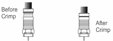
6 Attach compression tool to compress fitting onto cable. Do not use excessive force. Compress only until black band is fully reduced..
7 Cut and remove excess inner core extending beyond front, leaving only a small amount extending.
No braiding should be sticking out the rear of the connector, that causes signal loss. You should be able to pull on the connector with reasonable or light force without it coming off.


