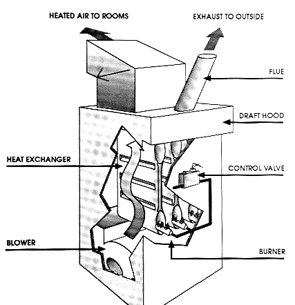
A gas forced-air heating system has a pilot light that ignites a burner inside the combustion chamber, creating heat that is then transferred to the furnace’s heat exchanger, a metal chamber around which air flows and is then heated. That heated air is then forced into the hot-air plenum and into the rooms through ducts. Gas fumes and carbon monoxide are vented through a flue in the roof.
The forced air gas furnace provides the option for an attached air conditioning unit and humidifier, part of a complete central air HVAC (Heating, Ventilating, and Air Conditioning) system.
Gas Furnace Diagram
This type of furnace produces heat through the combustion of natural gas in the furnace's burner. The heat produced from this process then passes through a heat exchanger. Air from your home's return air ducts is blown over the heat exchanger, thus warming the air. The furnace's blower then blows the warmed air into the ductwork, which carries and disperses the warmed air throughout the home.
Thermal Coupler
The thermal coupler is primarily a safety device that allows the pilot light to stay light, however, in the event the pilot light does go out, the thermal coupler prevents gas from leaking into the air. The thermal coupler shuts off the gas supply to the pilot of the pilot goes out. The heat from the pilot light keeps the valve in the thermal coupler open. If the pilot goes out, the metal cools and closes the valve. When a thermal coupler fails it tends to close the valve even when the pilot is burning and the metal warm. A thermal coupler is easy to replace and you will likely have to replace one on a regular basis.
note: If your gas furnace does not have a thermal coupler, then it uses an electronic igniter. The thermal coupler pilot light ignition system has been superseded by a modern electronic igniter system so that it is no longer necessary to have a pilot light.
How to Install a Gas Furnace Thermal Coupler
If the pilot light on a gas furnace will not stay lit the problem may be with a part called the thermal coupler. The thermal coupler is screwed into the gas control valve and has a thin wire which sets in the flame of the pilot. If there is no pilot light burning the thermal coupler tells the gas valve to shut off the gas supply.
- Locate the shut off valve on the gas line which goes to the furnace and shut it off.
- Locate the thermal coupler on the furnace. Look at where the pilot light is and trace the wire that sets in the flame of the pilot back to the gas control valve.
- Unscrew the nut which attaches the thermal coupler to the gas control valve. Remove the old thermal coupler and take it to the hardware store to make sure the right size replacement thermal coupler is purchased.
- Tighten the nut by hand which holds the thermal coupler onto the gas control valve. Use an adjustable wrench to tighten the nut the rest of the way.
- Place the wire end of the thermal coupler in the pilot the same way as the old thermal coupler. Usually only about the top 1/3 of the thermal coupler wire should be heated in the pilot light.
- Turn on the gas supply and re-light the pilot.
Electronic Ignition
The electronic ignition system in a gas furnace is a more efficient way to light the burners than the old pilot light system. The electronic ignition occurs typically in one of two ways, Intermittent Pilot, or Hot Surface Ignition.
The intermittent pilot system uses an electronically controlled high voltage electrical spark to ignite the gas pilot and then subsequently the main burners when the thermostat calls for heat.
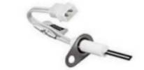
The hot surface ignition system uses an electronically controlled resistance heating element, not unlike a light bulb filament (and shown in the photo above), to ignite the gas burner.

Illustration:The Norton Model 601 is an example of a hot surface ignitor.
The Heat Exchanger
The heat exchanger on a furnace is the metal that separates the fire from the air stream. The heat exchanger was designed to keep the toxic fumes produces from burning gas separated from the clean heated air that is blown in your home. The inside of the heat exchanger allows the toxic flue gases produced from the burners to exhaust out through the furnace flue. The outside of the heat exchanger is where the cold air passes over, becomes warmed, and is blown throughout the ductwork of the home. The heat exchanger is the only wall separating the toxic flue gases from the supply air.
If a crack develops in the heat exchanger, there is a potential for carbon monoxide gas to leak over to the supply side and be blown throughout your rooms. Carbon monoxide gas is odorless. The human senses will not detect its presence. When the fan or blower is running it puts the outside area of the combustion chamber (heat exchanger) under positive pressure so there is no way the flue products could ever come out. Another problem with having a crack on one of these furnaces is that the flames will roll out because the draft air is leaking through the crack.
Inspecting the Heat Exchanger
Visually examine the heat exchanger with the aid of a flashlight. Many furnaces will have hair line cracks in the metal and sometimes welds will pop and leave a tiny hole. Small holes may not pose a problem. Look for a significant breach in the heat exchanger. When the furnace comes in an flames roll through the cracks then it is a significant problem.
In your visual inspection consider.
  1. Where is the crack?
  2. How big is the crack?
  3. How much air is leaking in out out of the crack?
  4. Is the crack actually in the combustion area or in the sheet metal of the frame?
  5. How will this crack affect the operation of the furnace?
  6. How can this crack cause combustion products to leak into the living space?
  7. Can you see light (blower removed) from the air side of the furnace?
  8. How does the crack compare to the burner openings and the flue opening on each end of the heat exchanger?
WARNING! Many experts recommend that you never rely on visual inspection alone to determine the safety of a furnace heat exchanger. carbon monoxide - CO - is a dangerous gas that can result in health problems and death. You don't want CO building up in your home due to a flaw in your furnace heat exchanger.
Ways to Find or Suspect a Leak in a Furnace Heat Exchanger
- Visual inspection with flashlight and mirror.
- Look at the heat exchanger through the Supply air plenum.
- Inspect at the furnace burner: for evidence of a heat exchanger crack or leak by watching for a change in flame pattern or color.
Recalls and Furnace Models Known to be Bad
- Lennox Pulse Furnace Safety Problems, Recall, Inspection, Advice
- Weil McLain Model GV Gas Boiler/gas valve CPSC recall/repair
- Goodman Furnace High Temperature Plastic Vent HTPV safety recall US CPSC notice
- Home Heating System Should Be Checked [for proper venting and for CO Carbon Monoxide Hazards - DJF]
Troubleshooting
Electronic Ignition
Here is an erroneous source that claims you can not manually light a furnace that uses an electronic ignition system. They are wrong. This proves that the Internet is full of misinformation. This youtube video shows me successfully lighting a furnace that has a faulty electronic igniter.
- screenshot of web site with false (or in some cases false which is why they should not state it as an absolute) claim.
- view this youtube video of me manually lighting this furnace by flame.
There are safety concerns with doing this so do not try it yourself. On this particular furnace design it was simply one step in a multiple step troubleshooting procedure. Other safety components had already been verified and the control board tested.
On the hot surface ignition gas furnace check the igniter using an Ohm meter to make sure it has resistance. If no resistance is read (open circuit) then the igniter is broken or cracked and needs to be replaced. Also ensure there is a proper ground to the board so that is not "floating" from one leg to the other. There should be 24 volts on a single leg which is what you need on the electronic ignition gas furnace controls.
Furnace Pressure Switch
The switch is near the draft inducer motor, which is responsible for moving combustion byproducts out. The pressure switch is activated by vacuum pressure.
Early systems have a single vacuum pressure switch. When vacuum pressure is present it closes the connection and when there is insufficient vacuum pressure the connection is open.
You can draw air though the vacuum line while an Ohm meter is connected to see if the switch is mechanically functional. You can connect the Ohm meter and then turn on the furnace. Once the draft inducer is active then the resistance value of the switch will change, typically from an open circuit to a resistance value relatively low.
If the switch is good but not activating during attempted operation of the furnace, then the draft inducer motor might have failed to turn on (if your furnace has one) or there could be penetration in the heat exchanger causing loss of induced vacuum pressure in the chamber.
Draft Inducer Motor
The induced draft or forced draft motor is used to force toxic gas out the vent. Some furnaces have a forced draft system while others have an induced draft design. The difference being the forced draft blower blows air through the heat exchanger while the induced draft motor pulls air through the heat exchanger.
Furnace Control Board
The furnace control board is responsible for governing the operation of the furnace. Your furnace may have one or more control boards depending on age and design. Some old pilot light furnaces do not use a furnace control board. The furnace control board design was introduced late in the thermal coupler pilot light furnace type.
Basic control board operation:
- triggered by the thermostat to control furnace (on/off/blower stage)
- interprets safety sensors such as the furnace vacuum pressure switch
- starts the ignition system, whether its a spark generator, glow coil or pilot light
- turns on or off gas supply to the burners
- governs operation until triggered by thermostat, a problem is detected, or a timed cycle duration is achieved
