Difference between revisions of "Icom IC-7600"
| Line 1: | Line 1: | ||
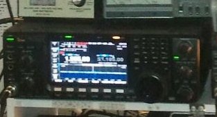
The Icom IC-7600 covers the 160 to 6 meter amateur bands. It utilizes IF-DSP technology and selectable roofing filters at 3kHz, 6kHz and 15kHz. Like the IC-7700 and IC-7800, the IC-7600 uses dual 32-bit floating-point Texas Instruments DSP chips with one for the radio and the other for the spectrum scope. This display is a 5.8 inch color WQVGA LCD. | The Icom IC-7600 covers the 160 to 6 meter amateur bands. It utilizes IF-DSP technology and selectable roofing filters at 3kHz, 6kHz and 15kHz. Like the IC-7700 and IC-7800, the IC-7600 uses dual 32-bit floating-point Texas Instruments DSP chips with one for the radio and the other for the spectrum scope. This display is a 5.8 inch color WQVGA LCD. | ||
| + | |||
| + | [[File:showIcom7600.jpg]] | ||
Status: Currently on the market as of 2017, still in production. Replaces the [[Icom IC-756 Family]] of transceivers. | Status: Currently on the market as of 2017, still in production. Replaces the [[Icom IC-756 Family]] of transceivers. | ||
Revision as of 02:43, 10 November 2017
The Icom IC-7600 covers the 160 to 6 meter amateur bands. It utilizes IF-DSP technology and selectable roofing filters at 3kHz, 6kHz and 15kHz. Like the IC-7700 and IC-7800, the IC-7600 uses dual 32-bit floating-point Texas Instruments DSP chips with one for the radio and the other for the spectrum scope. This display is a 5.8 inch color WQVGA LCD.
Status: Currently on the market as of 2017, still in production. Replaces the Icom IC-756 Family of transceivers.
- Receive Range 1: 0.030-60.000 MHz
- Receive System: Single receiver
- Dual Watch: Yes
- Roofing Filter Capability: Yes
- Roofing Filter Bandwidth: 15/6/3kHz
- Third Order Intercept (IP3): Over 30 dBm
- Transceiver Input Voltage: 13.8 Vdc
- Transceiver Maximum Current: 23.0 A
- Antenna Ports: 2
- Computer Connection Type: USB or CI-V interface
- Digital Mode Audio Input/Output: USB or 8-pin DIN
- Voice Synthesizer Capability: Yes
- Radio Dimensions: Width 13.375", Height 4.563", Depth: 11.000"
- Weight: 22.000 lbs.
- SSB/CW Maximum Power: 100 W
- SSB/CW Minimum Power: 2 W
- AM Maximum Power: 30 W
- AM Minimum Power: 1 W
Contents
Ver.2.00 Firmware
Tip: The first time you update, thoroughly read the Section 14 (UPDATING THE FIRMWARE) of the IC-7600’s instruction manual and information for firmware 2.00 on Icom Co. Support page. The firmware can be updated using a USB-flash drive.
Some new features:
- point and click the mouse for Click-and-Listen receiver control.
- Waterfall screens
- additional functions added to the spectrum scope
- APF AF Level setting
- CI-V commands for antenna control, logging software and RIT/DELTA-TX
- TX Delay (HF/50M) settings for variable delay time
- Standby setting to remotely turn ON the IC-7600 using the REMOTE jack.
- MOS-FET is now the default value of SEND Relay Type
Operating
Memory Channel
SAVE:
- Set the desired frequency, operating mode and filter width in VFO mode.
- Select channel # using up and down arrow keys or set
- Push and hold [MW] for 1 sec. to program the displayed frequency, operating mode
DELETE:
- Select memory mode with [VFO/MEMO].
- Push [MEMORY] (F-4) to select memory list screen.
- Select the desired memory channel with the up and down arow keys
- Push and hold [CLR] (F-5) for 1 sec. to clear the contents.
SELECT:
- Besides using the up and down arrow keys to scroll though the channels in memo mode you can go direct to channel
- IN MEMO mode press [F-INP] and enter number, then press either the up or down arrow goes directly to channel number
- press [EXIT/SET], [F-4], and hold [F-1] Roll and turn VFO to scroll though list on LCD, press [F-3] select to go to channel
MARS / Extended Transmit and Receive
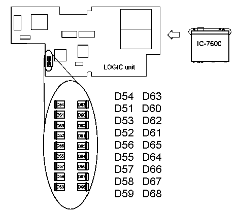
MARS/CAP Mod: IC-7600
RX Frequency Coverage Expansion
- remove D52, D53, D54, and D55
TX Frequency Coverage Expansion
- remove D56, D57, D58, and D59
offers: 1.6 - 30MHz and 51 - 54 MHz
5MHz Band Operation
- remove D62
offers: 5.255 - 5.405 MHz
Non-Icom Amplifier Connection
The ALC input level must be in the range 0 V to – 4 V. The transceiver does not accept positive volt-age. SEND RELAY type menu item (in the ACC set mode menu) which allows selection of the OMR-109F relay (LEAD) or a MOSFET interface (MOS-FET). The MOSFET option is rated at 250V/0.2A AC/DC, non-inductive. If the amplifier's open-circuit keying-line voltage is above 16V but below 250V, this option can be selected.
ACC set mode
Send Relay Type: Selects the switching relay type for [RELAY] from Reed and MOSFET. Select the suitable relay type when connecting a non-Icom linear amplifier.
- Reed - Use mechanical relay. (16 V DC/0.5 A max.; default)
- MOS-FET - Use semiconductor type relay. (250 V/200 mA max.)
Menu: SET -> ACC -> SEND Relay Type
The IC-7600 can key an amplifier circuit up to 250Vdc at 200 mA, select the correct keying mode via the ACC set menu.
With the Firmware Update Version 2.00 “MOS-FET” is now the default value of “SEND Relay Type.”
Use with SB-200 / SB-221 Amplifier
So, theoretically, you can use the IC-7600 with your old Heathkit amplifier without the Harbach Soft-Key interface as long as you use the MOS-FET ACC mode. However, you are better off if you go ahead and install the Soft-Key interface. If you have the Soft-Key interface installed, thus reducing the key line to approximately 0.7VDC at 1.5mA, then you will want to use the Reed ACC mode.
The recommended configuration: Use Harbach Electronics SK-220 Soft-Key Keying Interface and on the Icom ic7600 ACC set mode = Reed.
see also: Heathkit SB-221 HF Amplifier
Accessories
- LDG M-7600 External Meter
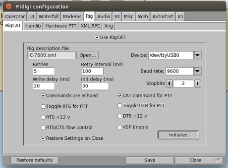
FLDigi and Rig Control
FTDI has two types of drivers for all supported operating systems. These are the virtual COM port driver (VCP) and the D2XX API driver. Since the FTDI VCP driver is built into the Linux kernel we will use it.
- FTDI cable from the "remote" port on the Icom to the USB port on the PC.
- In console type "lsmod |grep -i ftdi" look for:
usbserial 53248 1 ftdi_sio
If not seen, linux doesn't recognize the cat cable
In Linux, the VCP drivers will appear as /dev/ttyUSBx. How to verify the built in COM port:
dmesg | grep -i FTDI
The output on the terminal window should contain the following: (lots of output, look for specifics)
[    1.905014] usb 1-1.1: Manufacturer: FTDI
[   16.413787] usbcore: registered new interface driver ftdi_sio
[   16.413796] usbserial: USB Serial support registered for FTDI USB Serial Device
[   16.413826] ftdi_sio 1-1.1:1.0: FTDI USB Serial Device converter detected
[   16.414253] usb 1-1.1: FTDI USB Serial Device converter now attached to ttyUSB0
Now lets test to see if the computer is receiving cat data from the rig. Type this:
cat /dev/ttyUAB0
When you tune the VFO on the rig itself, you should see a bunch of ascii characers appear in terminal as output from cat - that means info is flowing from the rig to the computer via the FTDI cat cable. good.
Running fldigi as root the first time is recommended until everything working before worry about correcting permissions. Use this command to enable rig control before running fldigi
sudo adduser $USER dialout
to configure your IC-7600 to accept audio from the USB interface, decide whether your digital mode operation will employ DATA 1 mode (D1), DATA 2 mode (D2), DATA 3 mode (D3), or will be accomplished with DATA mode not in use. Then open the transceiver's ACC SET menu and
- set the appropriate entry's signal source to USB
- set the USB MOD level to 50% (you can increase or decrease this later to fine-tune the output level)
SET -> OTHERS -> CI-V Baud Rate          9600
SET -> OTHERS -> CI-V Address            7Ah
SET -> OTHERS -> Transceive              ON
SET -> OTHERS -> Output (fot ANT)        OFF
SET -> OTHERS -> USB Serial Function     Decode
SET -> OTHERS -> Decide Baud Rate        19200
USB Serial Function should be "Decode" and not "CI-V" if using rigcat!
In Software
- specify your transceiver's CI-V address in hexadecimal
- set the radio's CI-V Transceive parameter to off
- select the baud rate, parity, word length, and stop bits that match your radio's settings, do not use your radio's auto baud rate setting, as doing so can result in missed or garbled CI-V commands
Technical
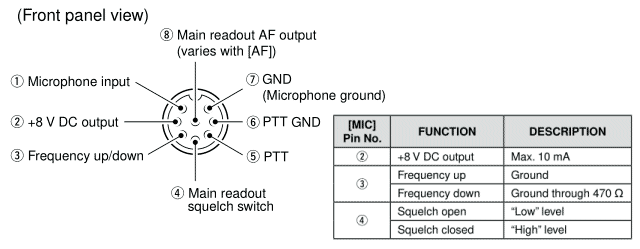
Microphone pinout wiring guide.

Caution: Do not short pin 2 to ground as this can damage the internal 8 volt regulator. DC voltage is applied to pin 1 for microphone operation. Use caution when using a non-Icom microphone.


