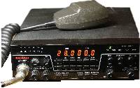
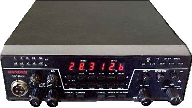
Clear Channel Ranger AR-3500
Clear Channel Corporation
Ranger AR-3500
made by: RF Limited / Clear Channel Corporation There is a 30W and a 125W version. The ranger is comparable to the Uniden President HR2510. |
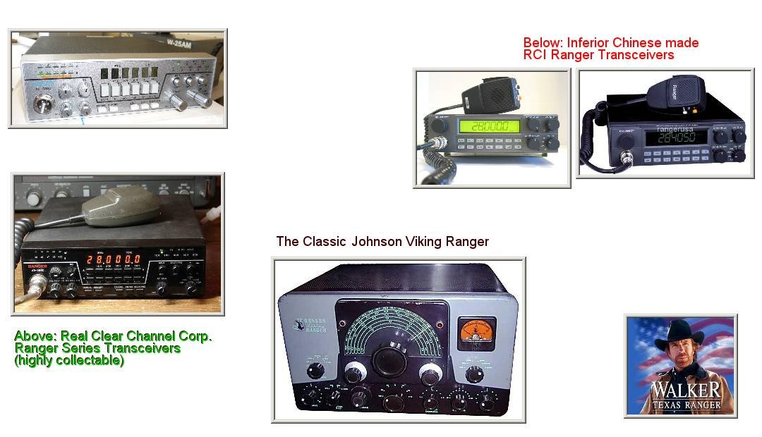
Look for the "Clear Channel" manufactured radios as opposed to the unrelated RCI brand radios.
4-pin mic jack model, later models were 8-pin |
Contents
POWER MOD ADJUSTMENTS
1 - VR-15 SIDEBAND POWER ------------------------- Turn fully clockwise -------------------------
2 - VR-16 AM POWER ----------------------------- Turn fully clockwise ----------------------------------
3 - VR-17 AM MODULATION ------------ Turn fully clockwise - Also cut diode 58 -----------
4 - TALKBACK in AM mode --------------------------------- Cut diode 73 ---------------------------------
There are mods allowing you to operate on 12 meters and receive down to 3 MHZ.
Used Market Value
These radios appear for sale at custom shops, Craig's List, and eBay on occasion but are not readily available because only a limited number were produced and owner's tend to hang onto them. Below is a sales record for used 100w models with or without mods. They have been spotted in Truck stops for up to $500 which is certainly excessive for used market value.
Clear Channel Ranger AR-3500 10m transceiver
-------------------------------------------
$110		unknown possibly working (sold used in 2015)
$233		needs repair may transmit unknown (sold used in 2015)
$255		Fully functional 100w model (sold used in 2015)
$260		functional with display problems (sold used in 2015)
$300		excellent condition (sold used in 2015)
$332		Used working with cosmetic flaws on faceplate + Turner M +3 mic (sold used in 2015)
-------------------------------------------
Distinguish 30w from 100w model
The 100 watt model has the amp stage in place of the rear heat sink and is much larger. This appears as a large box on the rear with large heat sink fins.
If you own the 100 watt model, it has been wisely recommended that you attach a cooling fan to help dispense with heat on the fins in the rear. The cooler you can keep the amplifier stage the longer your radio will operate. Furthermore, it is not necessary to run this radio at full power. If you step the power back about 20% you will gain four times that in operating life.
Early Ranges used a 4-pin microphone jack that was compatible with 4-pin Cobra CB radio microphones. Clear channel then switched to an 8-pin microphone jack with microphone that offered up and down buttons for channel change. An 8-pin mic doesn't mean that it will scan. The scanning board was an extra add-on. The number of pins on the mic jack is NOT a way to discern the model power output.
Optional Addons
There were some optional add-on boards available for the Clear Channel Ranger AR3500.
- Frequency scanning board
- SP-1 speech processor board
- CW-1 variable RF power board
History
Clear Channel Corporation developed the Ranger AR 3300 and Ranger AR 3500. They were built by Nissei of Japan. The Clear Channel Ranger radios have nothing to do with the RCI Radios also marketed under the name "Ranger." RCI is a Chinese company, and has no affiliation with Clear Channel.
In 1982, RF Limited started developing the Ranger AR-3300 and by April 1984 they had it on the market. The AR-3300 was Clear Channel Corporation's first product, although it was a flawed product that had issues. The issues with speech modulation were quickly cleared up on subsequent units. By the time the AR3500 rolled out, many improvements had been incorporated producing a solid 10-meter HAM radio.
There are AR-3500 radios in both 30 watt and 100 watt models. It is believed that the 30 watt lower power models were actually born 100 watts and were factory modified to lower the transmit power. Then owners would have to purchase a 100 watt upgrade from a 3rd party.
There are also AR-3500 units with 4 pin microphone and 8 pin microphone jacks. Later units were made with the 8 pin jack.
Disambiguation
What's in a name? That which we call a rose.
Ranger 2950 and 2970 are NOT Clear Channel radios and have no relation to their product going by the same name "Ranger." RCI Company, aka Ranger Communications Inc. has no relation to Clear Channel Corp. Ranger radios (RCI radios) makes 10, 12 meter Ham radios and gray market 11 meter CB radios. RCI radios are inferior low-end Chinese made and have no collectable value.
One has to understand that the Chinese knockoff company is using "Ranger" as a company name, whereas Clear Channel produced a couple models of radio using the name "Ranger." One is part of a company name, the other is part of a product name. Yet, there seems to be a lot of confusion among people concerning the name "Ranger."
Ranger Communications, Inc. aka RCI capitalized on Clear Channel Corporation's failure to trademark their Ranger model name. This gave the new RCI company some name recognition even though it is the result of confusion. RCI quickly sent their model 2900 to the market where some unsuspecting consumers thought they were getting an updated AR-3500. The 2900 was a failure and RCI later released models 2950, 2970 and also by a third name, Sommerkamp TS-2000 DX. These RCI units covered a wider frequency span than the Clear Channel Radio, from 26MHz - 32Mhz once modified. However, it is still an inferior radio made with low-end Chinese components.
Ironically, another company had used the name "Ranger" for a model of radio clear back in 1954. E.F. Johnson company produced a big clunky tube transceiver known as the Johnson Viking Ranger. It is a beautiful old rig that was also available in a "build it yourself" kit form. As collectable as the Clear Channel Ranger is to 10-meter enthusiasts, the E.F. Johnson Ranger is even more so to antique radio collectors.
User Guide
CONTROLS AND FUNCTIONS
The Ranger radio provides a variety of capabilities. To help you take advantage of those capabilities, the front panel controls are designed for convenience and ease of use. Their functions are described below.
1. RF LEDs indicate the amount of transmitted power. As the LEDs light across the scale, they show the relative power of your transmission signal.
2. S LEDs indicate the signal strength of the signal you are receiving. As the LEDs light across the scale, they show the relative power of the signal.
3. CLARIFIER is a fine tuning control. You can adjust a frequency - 500 Hz for best reception.
4. RESET is on the on/off control for the radio's backup voltage power. When this control is turned on, there is enough DC power to maintain any information you have saved in memory. Turn the control clockwise until you hear a click to turn on the backup power. If you turn this control off, anything saved in memory is erased. SQ (squelch) is a second function of this control. Use it to silence the background (white) noise, to adjust the transceiver's ability to receive signals, and to control automatic scanning of the memory. Turn SQ clockwise to silence background noise. Turn SQ counter-clockwise to increase the Ranger's ability to receive weaker frequencies. This control also starts and stops automatic scanning of frequencies saved in memory. Turn SQ clockwise to initiate automatic scanning; turn it counter-clockwise to stop automatic scanning of memory (after pressing the MEMORY button).
5. MIC GAIN increases or decreases the power of the microphone amplifier circuit. To increase its gain, turn the control clockwise; to decrease gain, turn the control counter-clockwise. For the optimum setting, press the PTT button and turn the control clockwise until all RF LEDs light. Then, turn the control counter-clockwise until the last LED just starts to flicker. 5A. ANL SWITCH -pull this knob to turn on automatic noise limiter.
6. RF GAIN adjusts the transceiver's sensitivity to both signals and background noise. It affects the distance at which you can receive a signal. Turn the control counter-clockwise to reduce the Ranger's sensitivity. This is particularly useful in areas where there is a lot of congestion (many signals close together on the frequency range). 6A. NB SWITCH -pull this knob to turn on noise blanker.
7. The frequency display consists of eight (8) numerical LEDs. It displays the frequency in use from 28.000.0 MHz to 29.999.9 MHz.
8. The momentary switches are used for a variety of purposes described below: SCAN Press upper switch to scan frequencies in an upward direction; press lower switch to scan frequencies in decreasing order. 100K, 10K, 1K, 100Hz (scanning increments) Press the appropriate upper momentary switch to select the scanning increment (i.e., 100,000 Hz, 10,000 Hz, 1,000 Hz, or 100 Hz). To change the frequency displayed, press the upper switch to increase the displayed number or lower switch to decrease the displayed number. Use the switches in this manner when selecting a specific frequency, saving a frequency in memory, or setting frequencies for split frequency operation. CH1, CH2, CH3, CH4, CH5 (channel selection) When saving a frequency in memory, press the upper switch that corresponds to the channel number that you want to assign to that frequency.
9. MANUAL is used before starting or restarting several procedures. If you are scanning frequencies, scanning will stop when you press this button. Press MANUAL before directly entering a frequency, before entering a new upper or lower frequency range limit, and before you begin the procedure for storing frequencies in memory or setting frequencies for split operation.
10. MEMORY scans the frequencies that you have saved in memory. If SQ is turned down (counter-clockwise), MEMORY scans to the next channel each time the button is pressed. If SQ is turned up (clockwise), channels are scanned automatically when the MEMORY button is pressed once.
11. CANCEL clears a frequency that has been assigned to a channel and saved in memory. Use the MEMORY button to display the frequency and press CANCEL.
12. ENTER is used when you are changing the frequency range or saving frequencies in memory. Press ENTER when you want the transceiver to accept the frequency displayed as the one you want to use. For example, if you are changing the frequency range, press ENTER once after you enter the upper frequency and again after entering the lower frequency. ENTER is used in the same way when saving your favorite frequencies in memory.
13. SCAN PRG is used when you want to change the frequency range of the transceiver. Press this button before entering the new upper and lower range limits.
14. Status LEDs provide the following information: RX lights whenever the AF GAIN is on and the microphone's PTT button is released. TX lights when you are transmitting (i.e., pressing the PTT button on the microphone). ST BY is not currently implemented. This LED will be used when additional accessories are available. SPLIT lights when you are using split frequency operation (the SPLIT button is pressed in).
15. Channel LEDs (CH 1, CH2, CH3, CH4, CH5) provide information about frequencies saved in memory. An LED flashes once when you save a frequency in memory by pressing one of the channel switches. When you scan memory automatically, each LED lights briefly as the channel's frequency is scanned. A channel's LED also lights when manually scanning memory and when that channel's frequency is in use.
16. SPLIT is pressed in when you want to use split frequency operation. Release the button (out position) when you want to resume normal operation.
17. SPLIT PRG is used when setting the frequencies for split frequency operation. The button should be out when you enter the receive frequency. Press SPLIT PRG in before entering the difference (number of MHz) between the receive and transmit frequencies. This button should be out when actually using split frequency operation.
18. + / - is used with split frequency operation. The button should be out when you are setting the receive and transmit frequencies. During actual operation, press the button in if the transmit frequency is higher than the receive frequency. The button should be out if the transmit frequency is lower than the receive frequency.
19. OFF/AF GAIN is the on/off and volume control for the Ranger. Turn the control clockwise until you hear a click to turn on the transceiver. Continue to turn the control clockwise to increase the volume; turn it counter- clockwise to decrease the volume.
20. MODE SELECTOR is used to select one of the following operating modes: FM (F3) Frequency Modulation AM (A3) Amplitude Modulation USB (A3J) Upper Side Band LSB (A3J) Lower Side Band CW (Al) Continuous Wave


